
Simple Hand wired 40% keyboard
Introduction
I’ve been a big fan of mechanical keyboards for a while now. I’ve a few keyboards with PCBs and made hot swappable boards but never attempted to build a hand wired keyboard. I was looking for something to do in terms of projects as I waited for my new MSLA printer, and take a rest from messing around with my MK3S. After doing some research and looking back into hand wired keyboards I decided to build my own and decided to write a short and simplified guide on how to build one. This will be pretty concise and not explain every aspect of hand wiring, but will cover the basics so that you can wire one up yourself.
Here are a few guides that I took gleaned information from:
Hand-wiring a custom Keyboard - Matt3o.com
Handwired Keyboard Build Log - Masterzen's Blog
A Modern handwiring Guide - Stronger, Cleaner, Easier
These guides are a lot more comprehensive than mine, they cover why and how things work, which is great but there is a lot of information crammed into those guides and I decided to create this guide as a more simplified version of those. This guide will explain to you as concisely as possible all that needs to be done to get a board running. The point of this guide is very much to show you how to get from point A to point B. If you want to learn more about why or how it all works, I recommend checking out Matt3o’s guide as it is very in-depth or any of the other ones I’ve linked above.
S.C.R.A.P. Board
I decided to call this the S.C.R.A.P. Board, which stands for Super Cheap Re-purposed Additional Parts Board. I tried to build this board for the least amount of money possible. I have a lot of left over things like switches, key caps, and just parts that have been sitting around in a ziplock bag, so I decided to use them to practice building a 40% Planck board. The reason why I decided to build a 40% as oppose to a 60% or something bigger is because I wanted to be able to quickly build this and at the same time I wanted to 3D print the case and plate quickly. My 3D printed can accommodate a 40% plate and case without having to print multiple pieces. The other reason being that since it’s only a 40%, the amount of parts required is limited and if I did make any mistakes or ruin anything it won’t be a humongous lost. The board didn’t cost me very much because I already have the majority of the parts, but in reality, all you need are the diodes, switches, magnet wire, keycaps, and the Proton-C. Yes, it could be possibly cheaper to just buy a Planck Rev.6 and EOTW case, but if you have spare parts, this is a fun way to use them.
Parts and Tools
This is a list of tools and parts that I needed to do this project, all the Amazon links are affiliated and I earn a small percentage when items are purchased through these links, this really just goes to helping me keep the site up. You don’t need to buy anything if you already have the majority of these things:
Tools:
1mm diameter metal rod or precision screw driver
Parts:
Prepping

Make similar loops on your diodes (I know this is a resistor) ;)
The first and most tedious task was making the loops on 40+ 1N4148 diodes. I use a precision screw driver but you can use something thinner if you have it. The point is to make a small enough loop that will fit over the leg of the switch, the smaller the loop the better because you won’t need to use as much solder. I’ve seen guides where loops are only made on one side of the diode. Most guides have the loop on just the side that isn’t black, but on my board I decided to make loops on both sides of the diodes. The picture above is a resistor, but the idea is the same.
The Proton-C has the option to add a little speaker so you can output audio from the keyboard, I soldered this in place as well. This is optional and not necessary.
Case and Plate
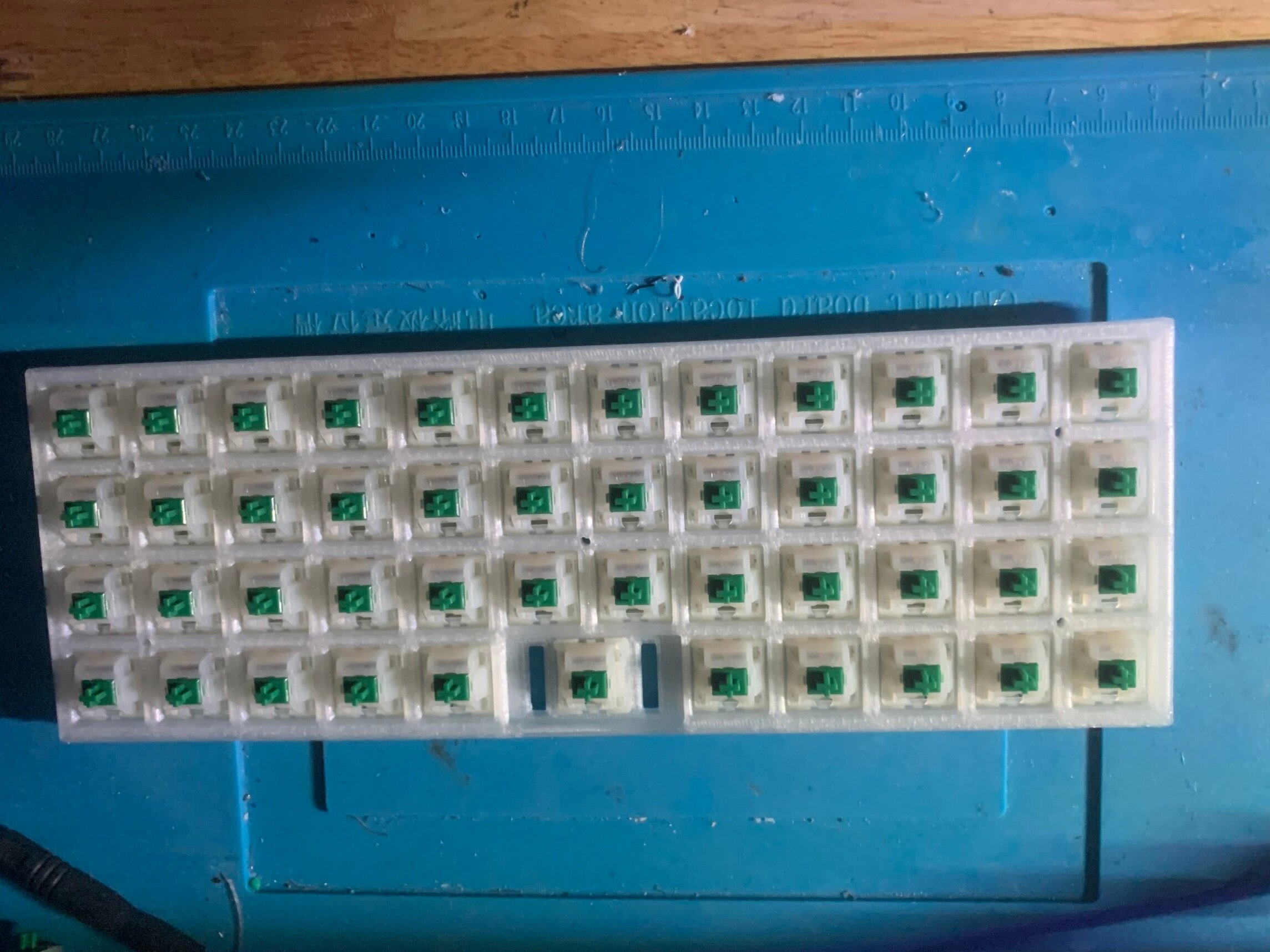
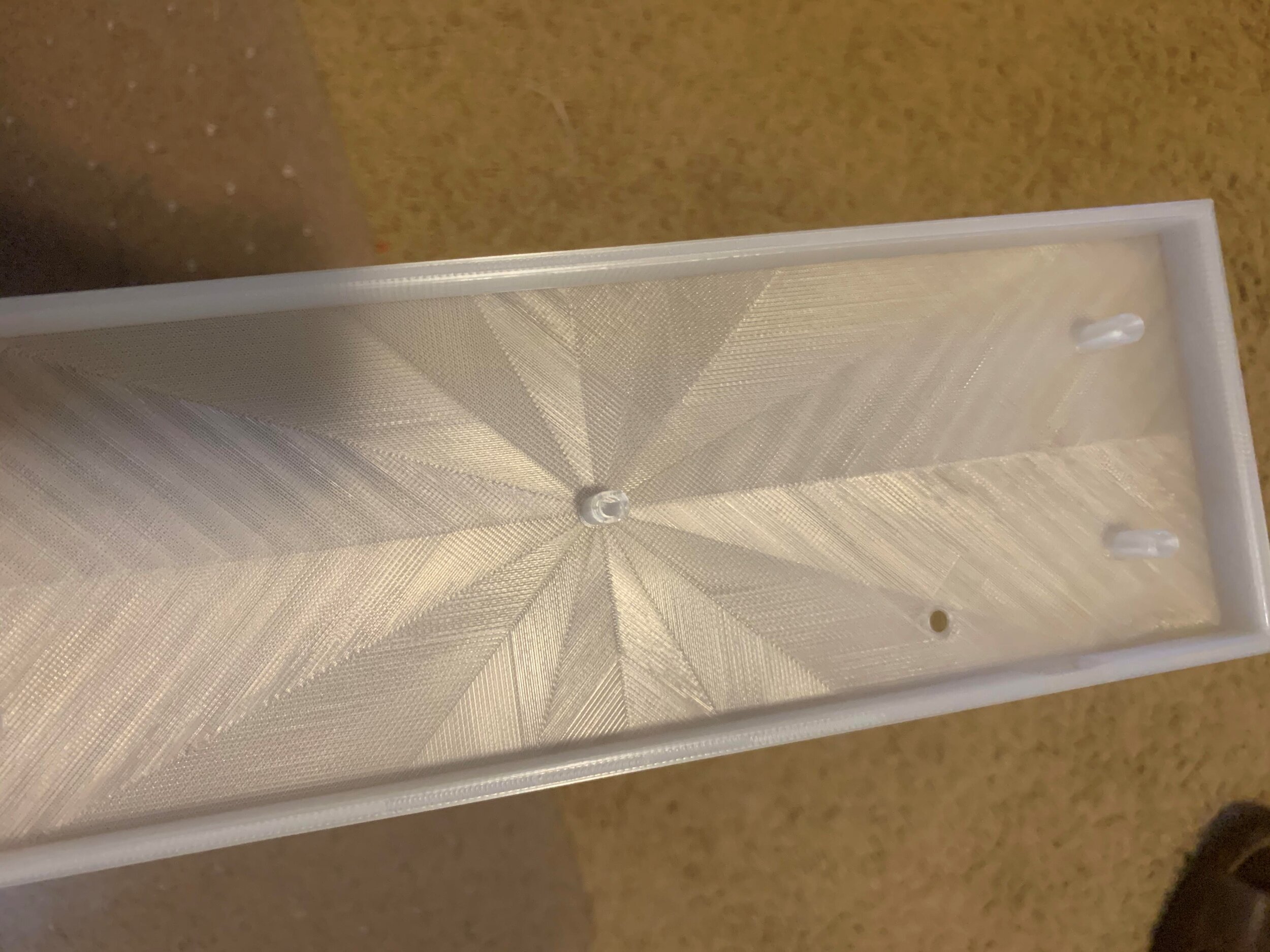
For the case and the plate on this project, I decided to just 3D print them, I did so with 100% infill using clear PLA filament. I included the model I used above in the parts list. I did initially try a thinner plate and different case, but it was way too flimsy since it was not really made to be 3D printed. This was the best case I could find and it is thick and sturdy enough to house the switches without much flex. Something about this case that was kind of annoying was the fact that the hole for what is usually the TAB switch is too tight and doesn’t fit the switch. I know my printer is accurate in tolerances and even tried to scale the plate up but for some reason that hole just didn’t fit. I ended up using the flush cutters on my switch and was able to get it to fit, This is not the best looking choice, but I thought it added to the DIY look of the board. Adding the switches to the plate was a fairly easy task, I think the most difficult thing was figuring out which orientation to have them go in. Most guides have the legs facing down, so I followed that. What I meant my “down” is if you were to look at the back of the keyboard the legs of the switch on on the bottom instead of the top. My pictures below give a better explanation.
Solder Diodes to Switch
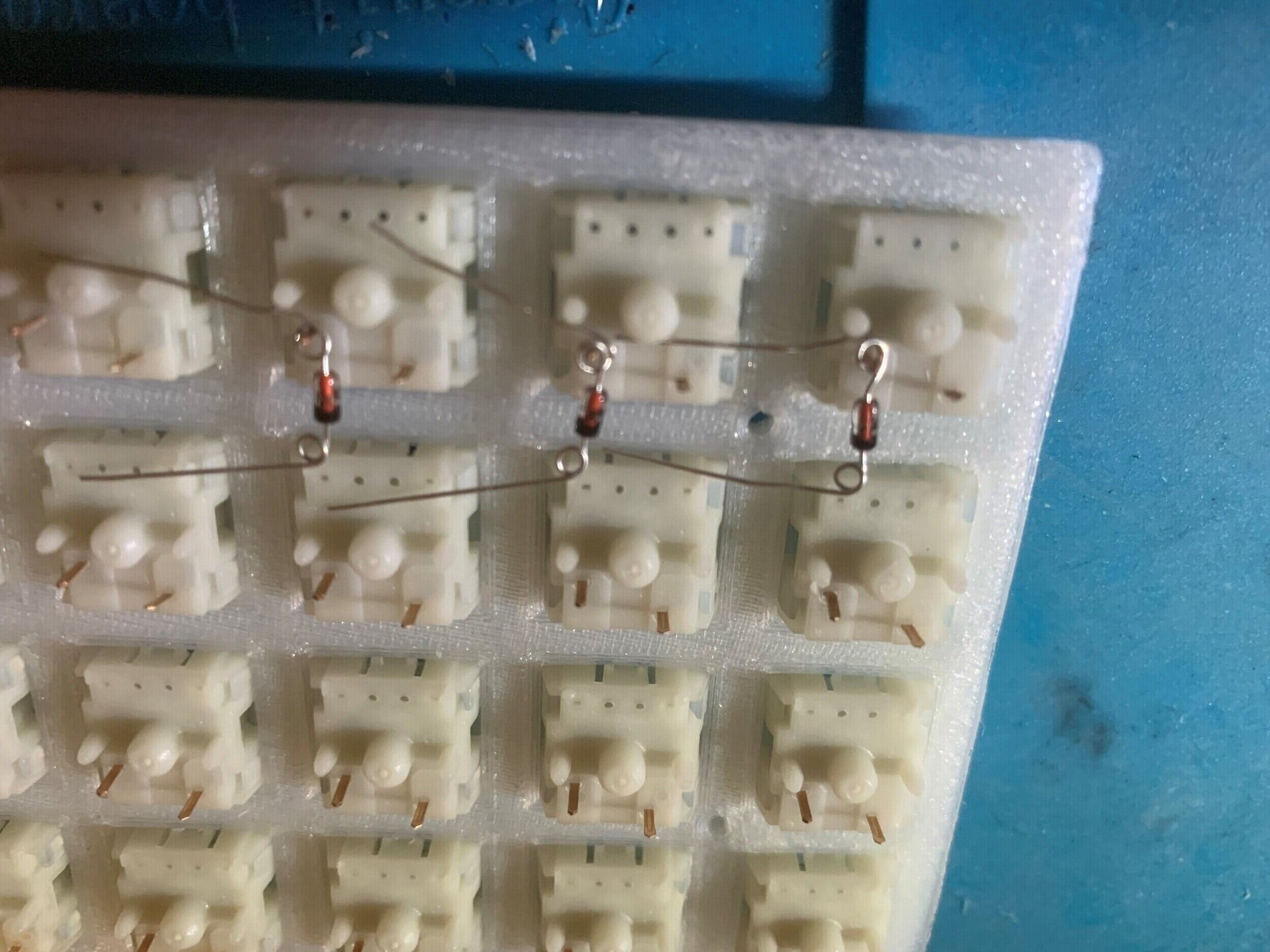
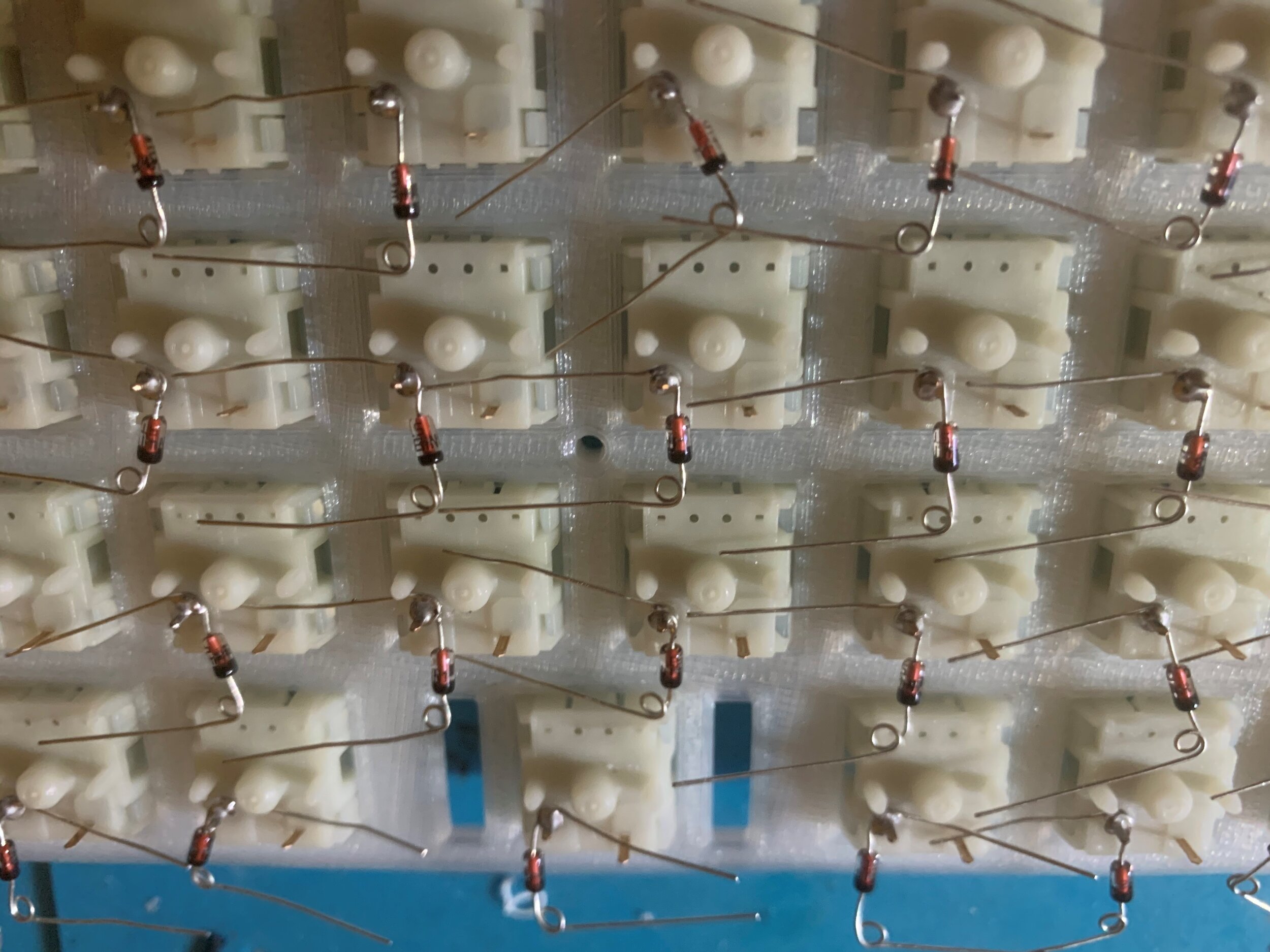
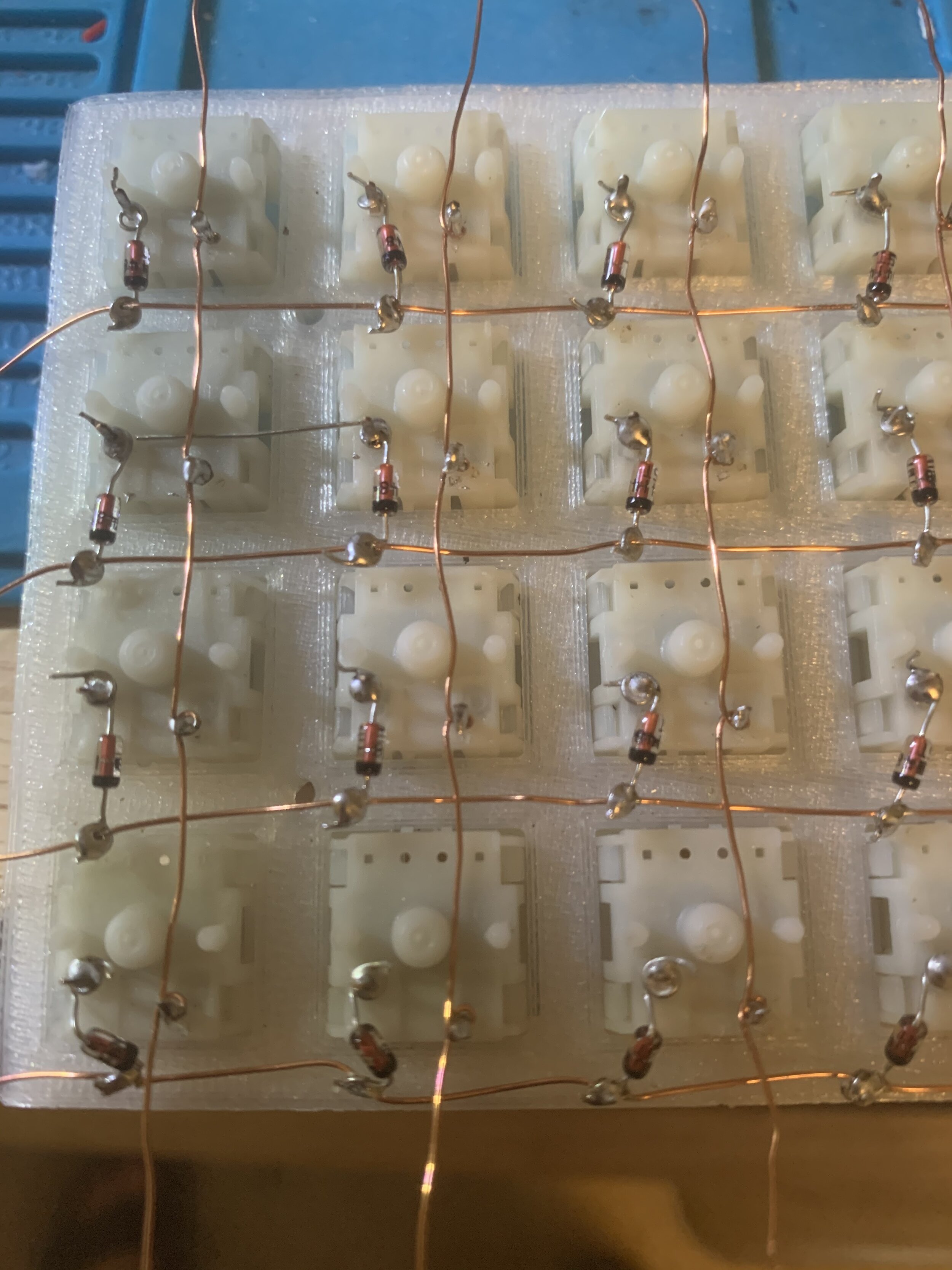
This process involves taking the diodes we’ve made loops with and putting them on the switch legs. A lot of the guides I’ve read have the diodes looped on the right leg when looking at the board, but I accidentally soldered them on the left side and haven’t seen any issues with it. I read another guide that mentioned it didn’t matter which leg you soldered the diode to as long as it’s consistent. You also want to make sure the diode is facing the right direction, black end should be out and red end should be soldered to the leg.
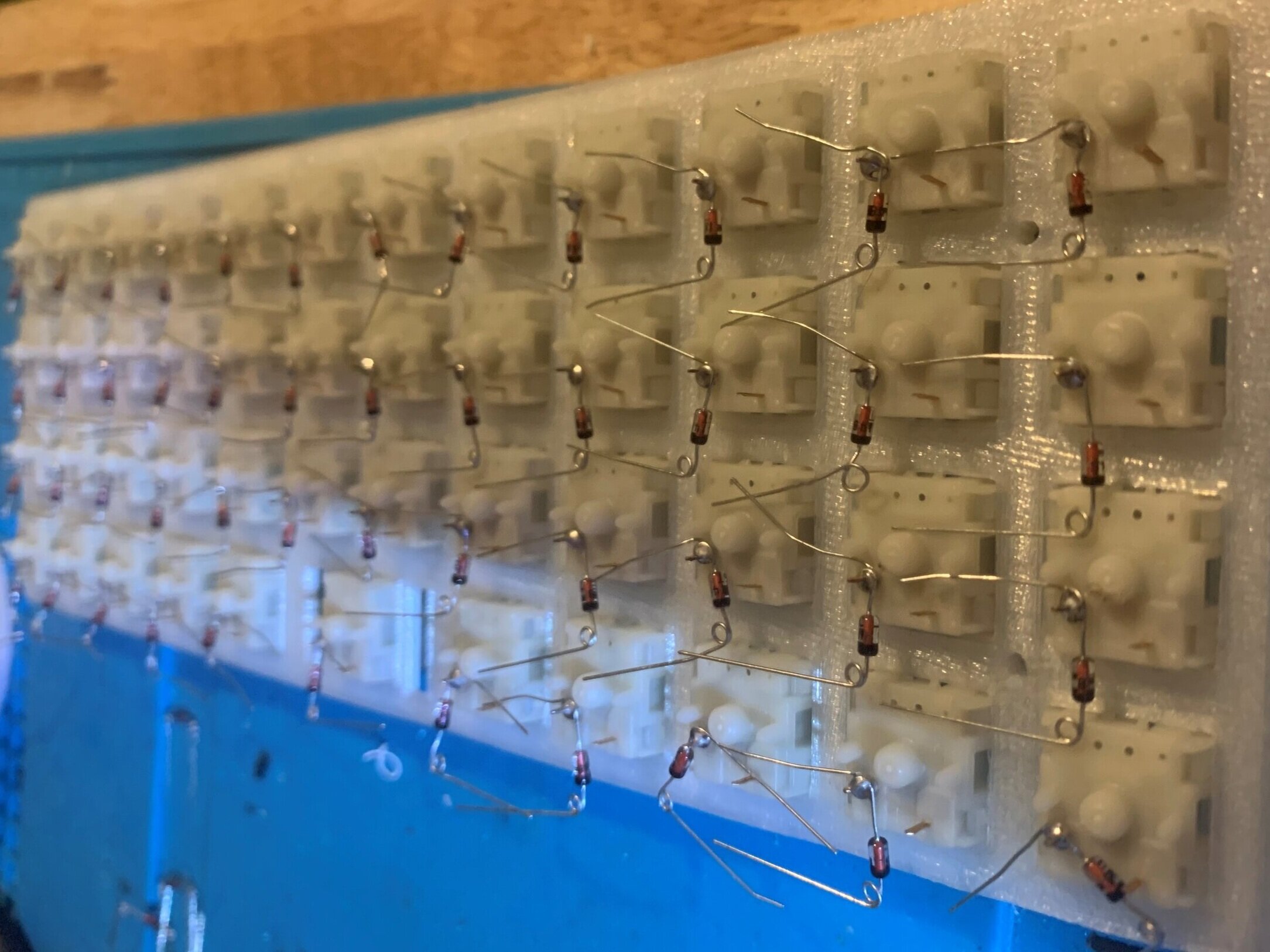
Wiring the Diodes
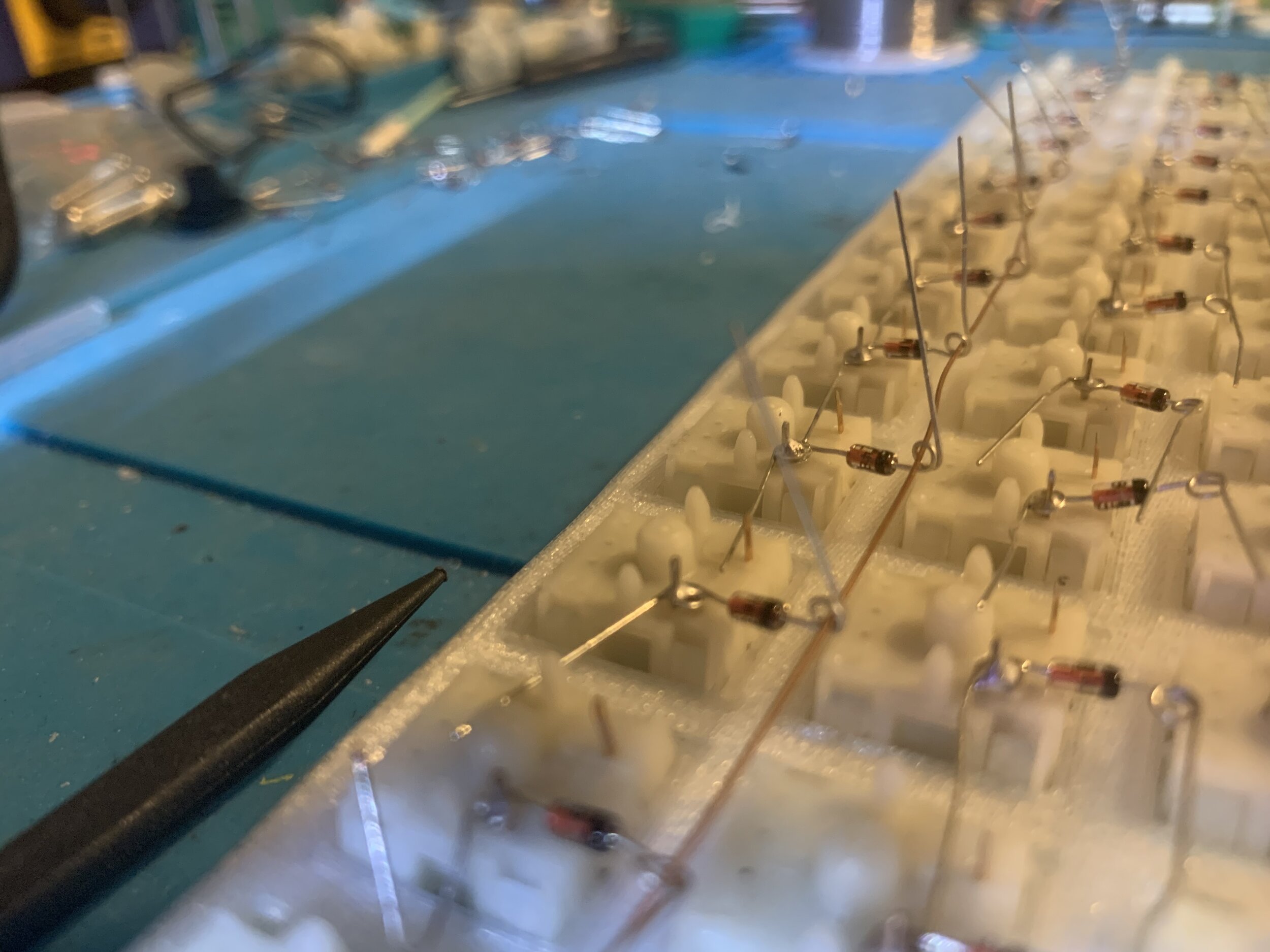
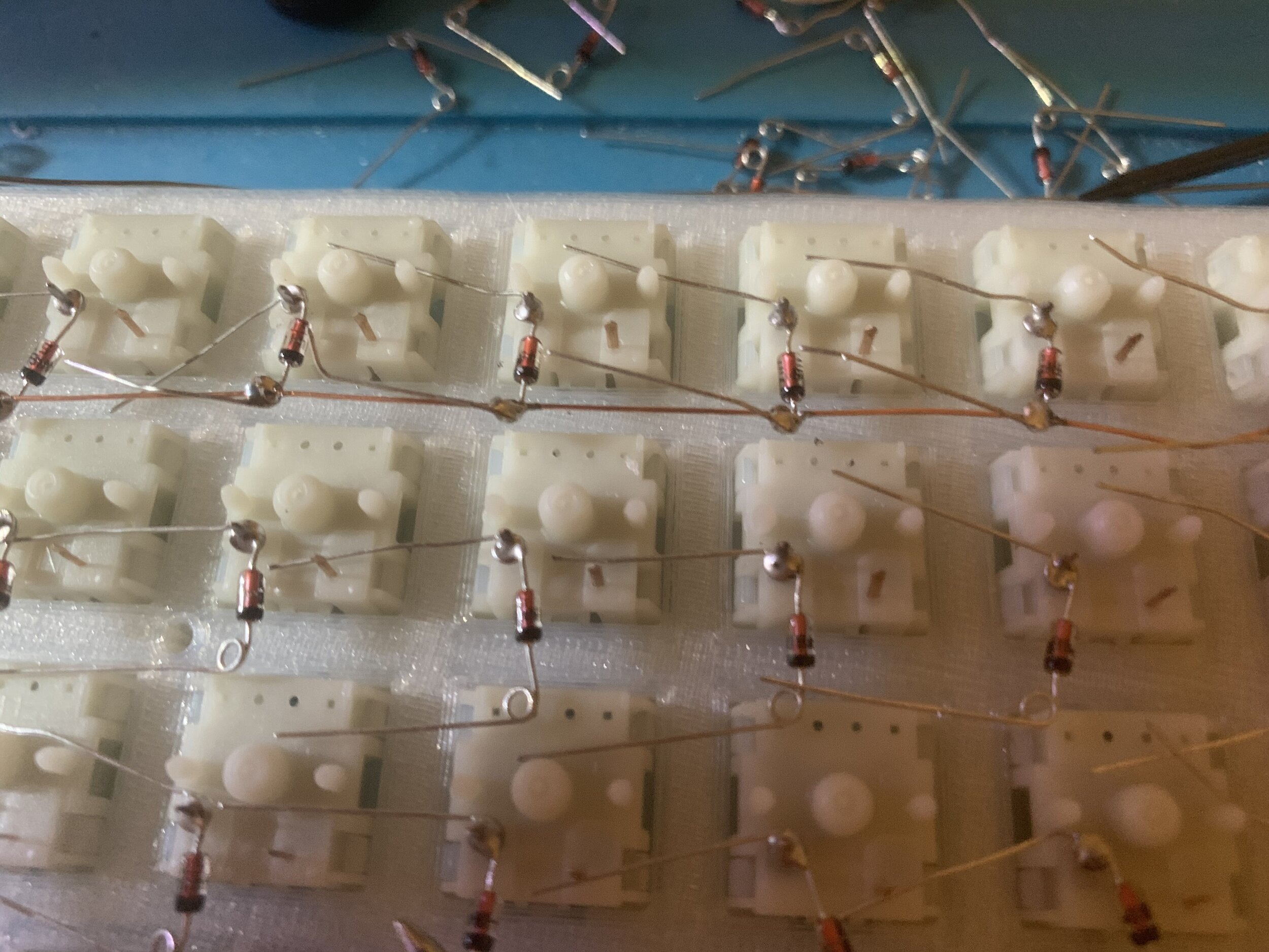
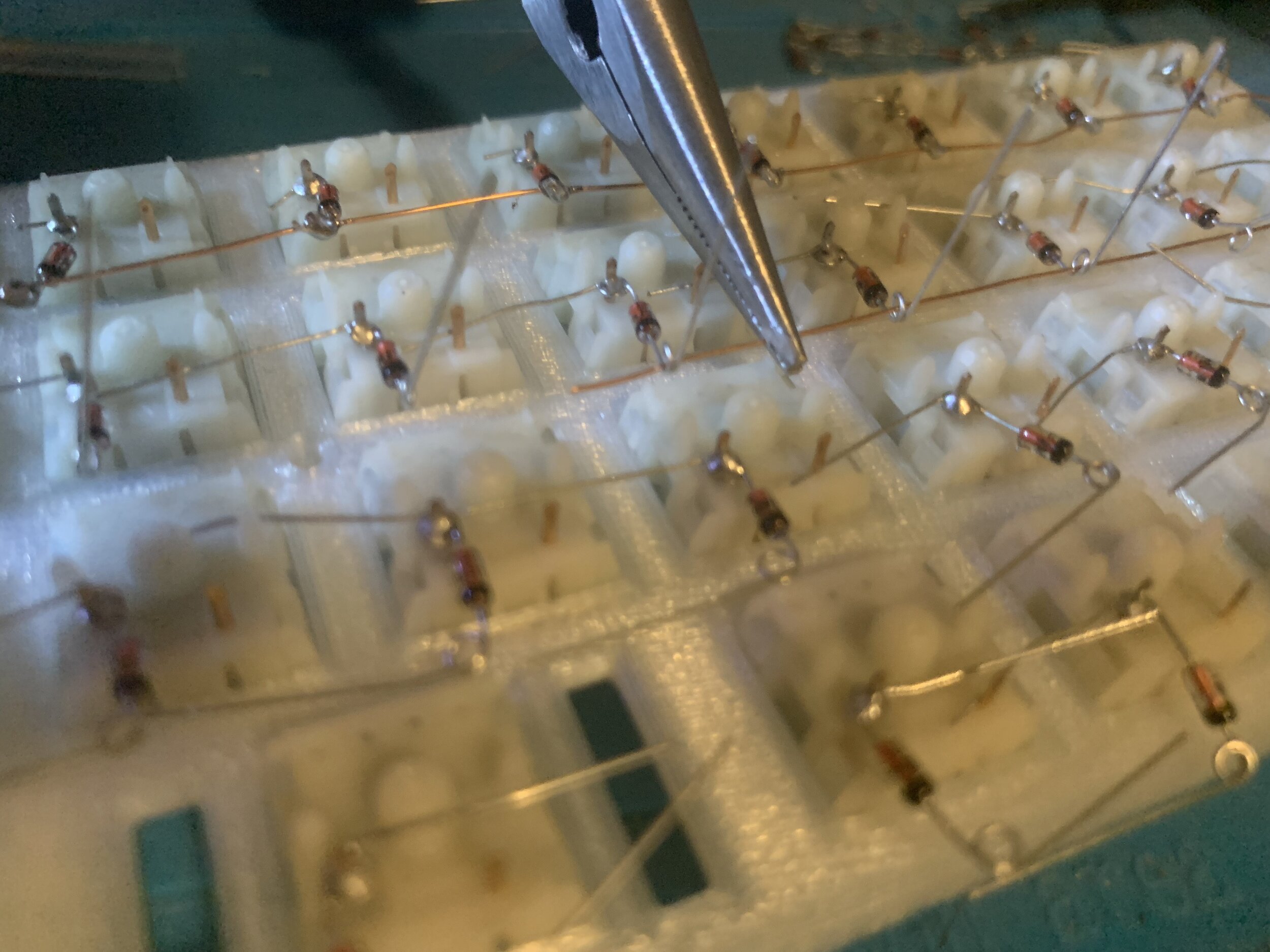
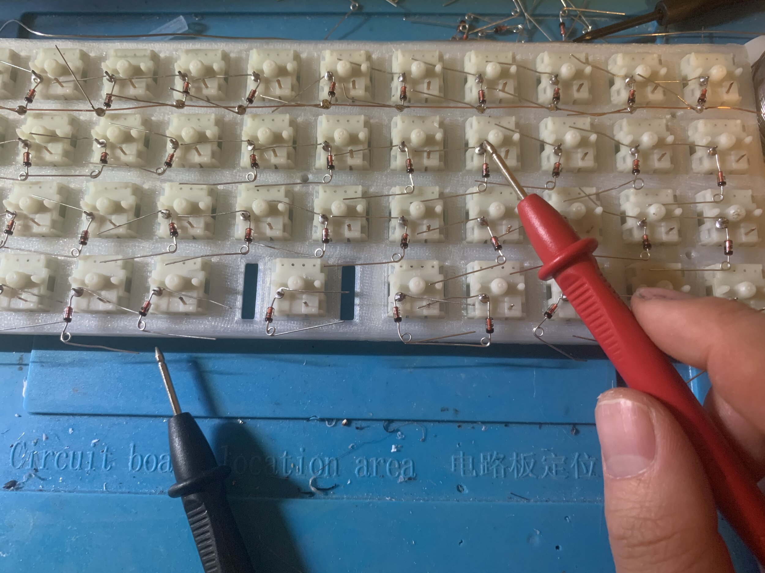
Once you’re done with soldering all the diodes to the switch legs, the next step is to solder the wire onto the diode. For this step I bent all the diode legs to be facing up (Refer to pictures above), because we’ll need to thread the magnet wire through each diode loop. Once the wire has been threaded through all the loops, keep about 10” of excess wire, I use this excess wire to connect to the Proton-C board. I fold the diode legs so they’re laying flat after the wire has been threaded. You’ll then have to start soldering each loop the wire is running through. Since we are using magnet wire it has a layer of enamel that keeps it from shorting, so you’ll need to have your soldering iron heat up the enamel until it melts. Something I noticed while doing this was that when you run the soldering iron across the wire it feels smooth, but once the enamel has melted it’ll squeak. After everything is soldered, you can snip off the wires coming from the diode to keep things neat. How I test to make sure that the row is functioning properly is by getting my multimeter and setting it to the “continuity” setting and touching the solder point from one end of the board to another. If it beeps, your row is functional. If it doesn’t beep, test each solder point to see if you may have not completely melted the enamel. This takes some time to do and if anyone knows a better way to melt the enamel, please share!
Wiring the Switch legs


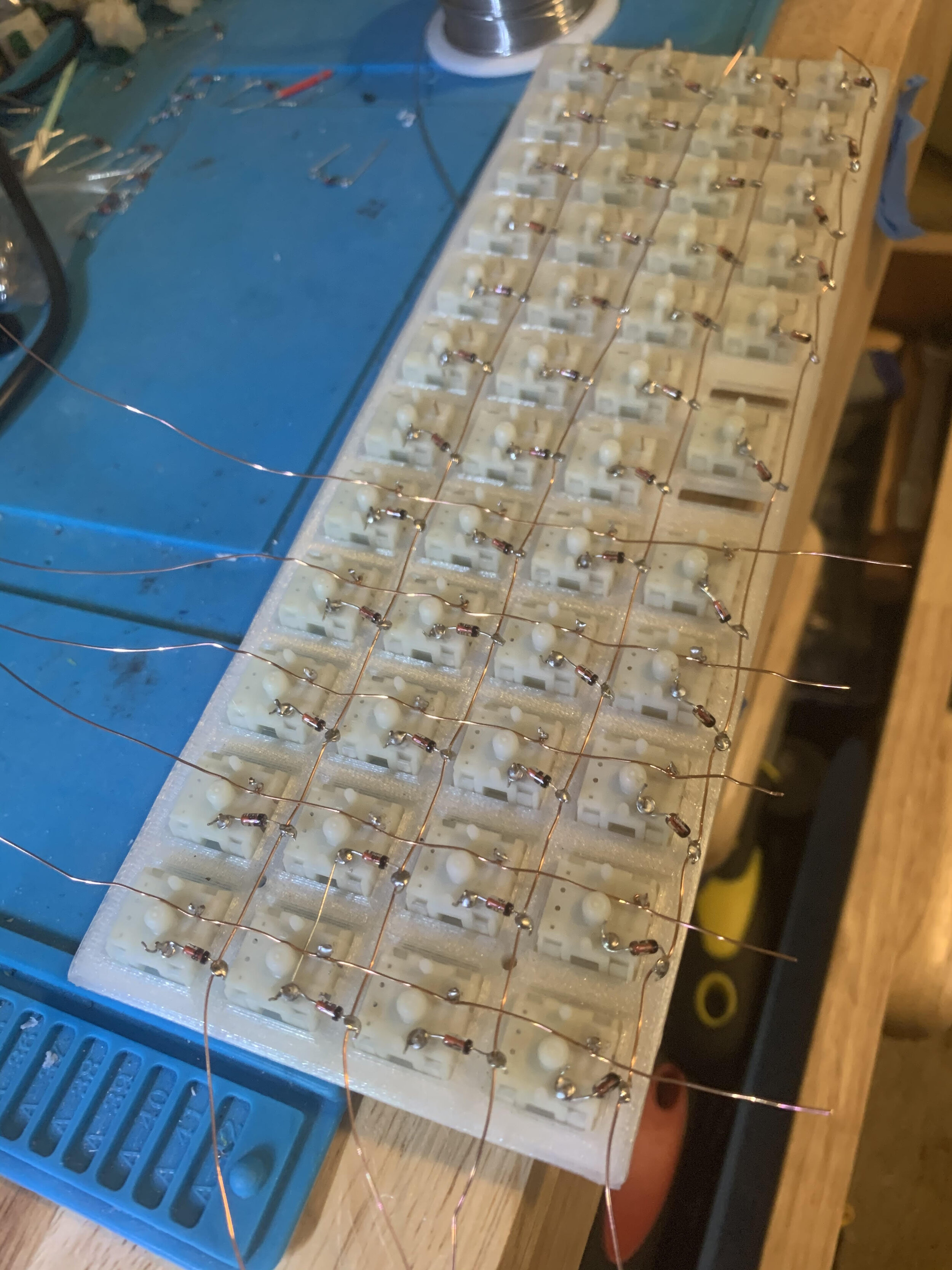
For wiring of the columns what I did was made a loop at the end of my magnet wire, place it over the leg of the switch (starting from the bottom switch and moving up) and just used my fingers to make a loop on each switch leg as I move up the column, pushing the wire down so it sits as flat as possible. After completing on column, I leave about 10” of excess wire. Soldering these were a bit more difficult. Again, you want to be able to remove the enamel from the wire, so you want to heat the magnet wire up and at the same time be careful not to melt the switch or any other surrounding parts. I usually rub the soldering iron on the magnet wire until I can hear squeaking and then add solder to the leg. Once you’ve completely soldered the column, do a continuity test again, touching the leg on the bottom switch where you just soldered the wire and the leg on the top switch and seeing if the column beeps.
Wiring the MPU Board
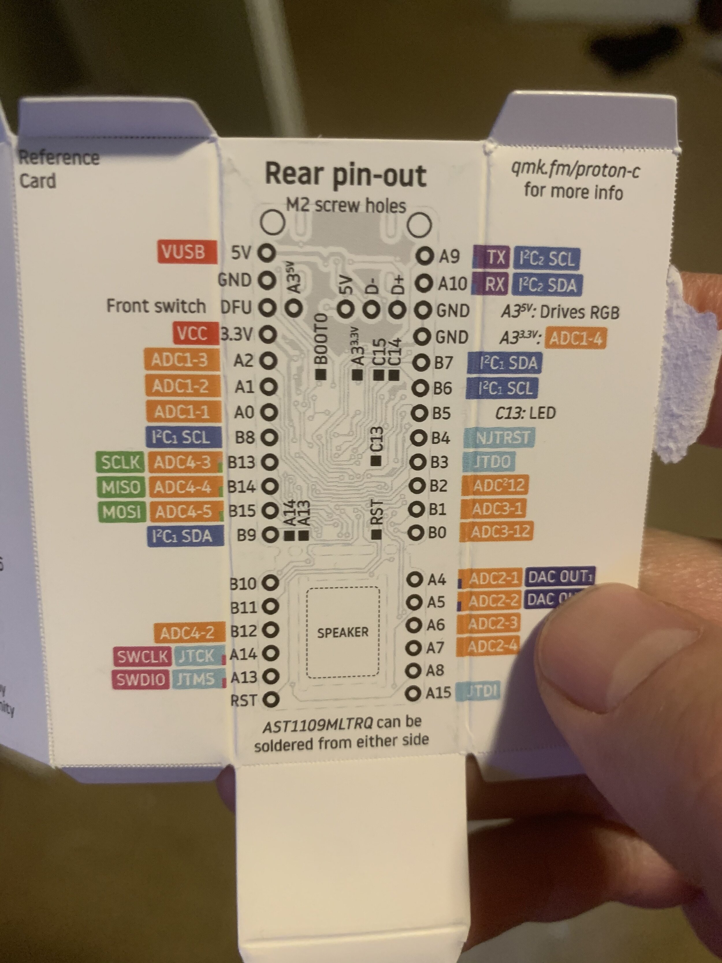
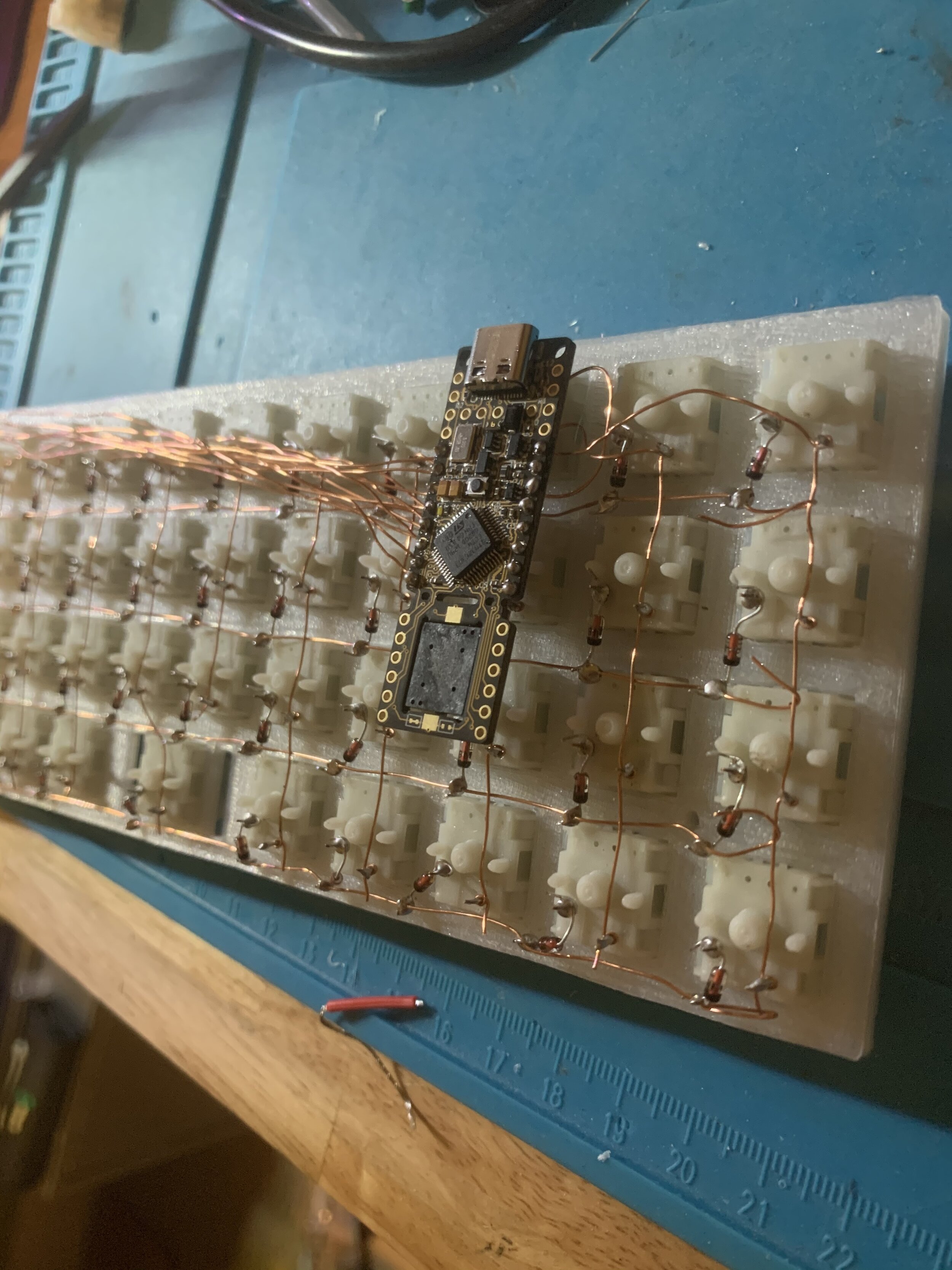
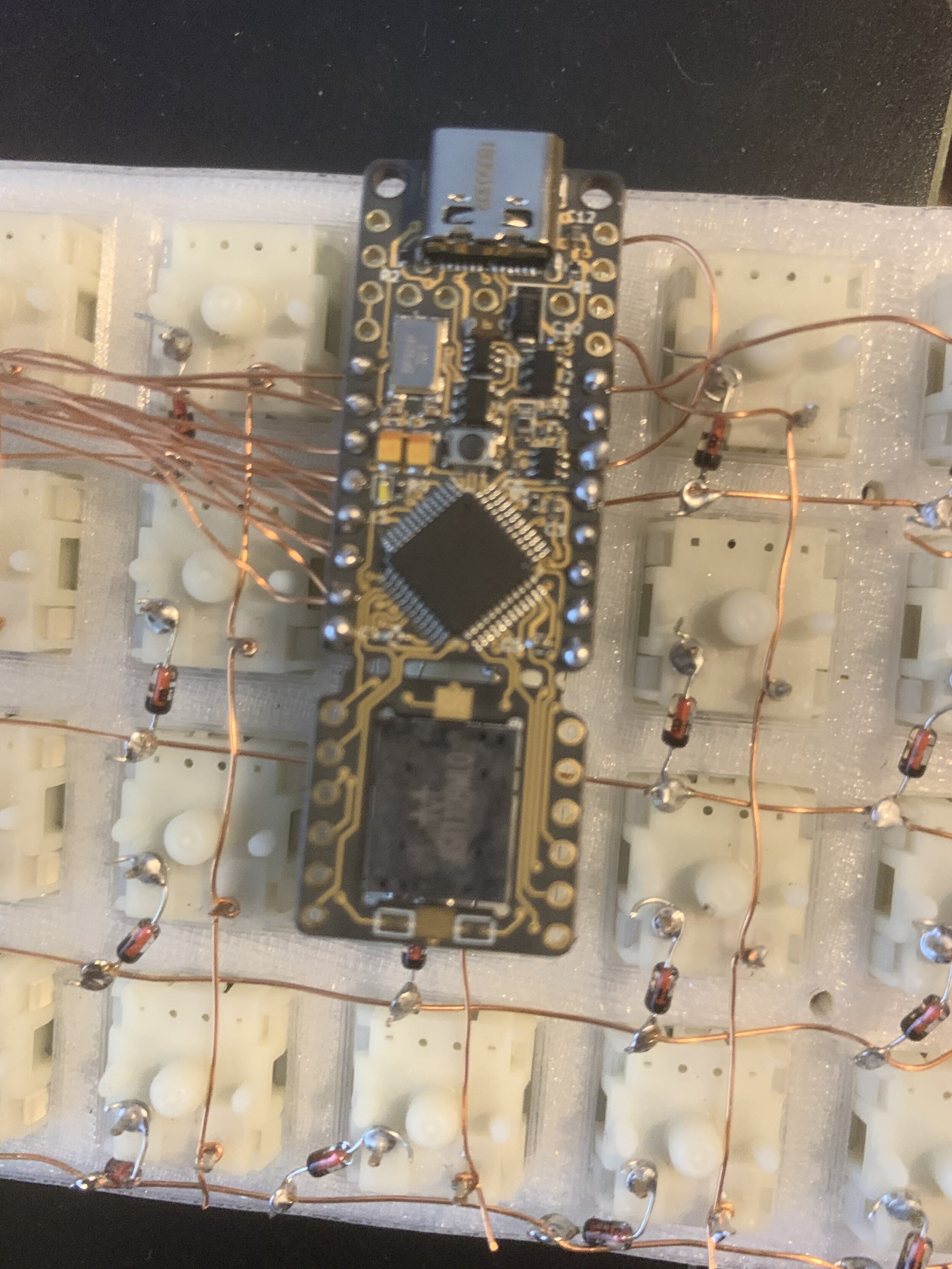
At this point you can do some wire management if you want. Remember that the magnet wire has an enamel coating, so there won’t be a short if you touch anything. I considered bending the row wires on itself and looping to the board, but since this was a proof of concept, I decided to be lazy and just run the wires in the easiest way possible. During this process try to be mindful of what pin each wire is going to and making note of it. In my case I used the following pins for my rows: B0, B1, B2, B3, and the following pins for my columns: B4, B5, B6, B7, B9, B15, B14, B13, B8, A0, A1, A2. After lining up the Proton-C to the opening for where the USB-C port was on the case, I soldered all the wires to their respective pins and snipped off the excess wire with a pair of flush cutters. I then went back using the soldering iron and pushed the wire and solder down so that the tip of the wire was covered with solder and making contact with the right pin hole. Again, I did a continuity test with my multimeter, checking each pin and their row/column to make sure I have continuity. This took a bit of time, but I was able to get everything functioning after a few tries.
Finished Build
Not the prettiest board in the world, but this was how it looked after I finished putting it together with the keycaps I had. I do plan on re-doing the board and print the case and plate in resin since FDM just doesn’t look as nice. Didn’t get a chance to take too many glamour shots of the board.

SCRAP Board
Software and Firmware
The software and firmware aspect of this build was a bit more involved than the build itself. I’m not going to get deep into it in this guide but the instructions provided by the QMK site are pretty thorough and helped me to get QMK setup fairly easy: The Complete Newbs Guide to QMK, once everything has been setup you’ll have to make the keyboard firmware. I’m using a Proton-C so the closest board I found was similar to mine was the Wulkan board found under: qmk_firmware\keyboards\handwired\wulkan, and I used that as the foundation for my board. The guide takes you through building your firmware the correct way, but I was a bit lazy so I simply went to the config.h file, made changes to what is defined as the ROWPINS and the COL_PINS to what pins I was using on the board and then I saved that file and built the keyboard firmware using the make wulkan:default:dfu-util command detailed in the guide. After you build the firmware you’ll need to flash it, there is a little button the Proton-C that if pressed will send the board into DFU mode which will allow the firmware to be flashed.
Conclusion
I know the software and firmware section is a bit thin, but that is because I’m also still learning QMK, I’m really new to this so I don’t know all the tricks, but as I learn more I’ll probably doing a more indepth write up of how to use QMK through CLI. I do hope that this guide will help anyone who have read other guides and thought that hand wiring was a daunting task. While it does take time and patience, I believe it can be done. My board that I built will not be a daily driver and honestly, it’ll probably be dismantled soon so I can take the time to rebuild a better and cleaner looking board, again this was a proof of concept and I just wanted to see if I was capable of putting it together. Let me know if there are any crucial things I may have missed of if there is anything I can do to improve on this guide!