
Building a Lily58
A few months ago I bought an ortholinear keyboard. If you don’t know what that is, here’s a short explanation from another website: “Ortholinear keyboards are a unique type of keyboard with a die-hard group of followers within the mechanical keyboard community. The non-staggered keys make for an interesting typing experience that is highly sought after.” I have found typing on a ortholinear keyboard to be very enjoyable. It didn’t take long to relearn the key positions and after a couple of weeks I was to typing my usual 93 WPM. My biggest issue with my board is that sometimes I feel like it’s a bit too small. Because the board is only about 14” long, it feels “cramp”.
I recently discovered ortholinear split keyboards, they have a similar non-staggered setup as my current keyboard but are also a bit more ergonomic. I did a lot of googling and research looking for exactly what I wanted. I ended up going with a board called the Lily58, it has 58 keys, options to add two small 0.91” OLED screens, hot swappable key switches, a rotary encoder which I use often on my current board. The iteration of my board has per switch LEDs along with 6 backlit LEDS known as the Lily68l. The more common Lily58 Pro and Lily58 doesn’t have the per switch LEDs, but for the most part they function the same.
Tools and soldering
For this project you need either a soldering iron or a hot air rework station. Honestly, I suggest you just pick up a cheap rework station to make the process easier. I timed how fast I as able to solder the diodes, SMD LEDs, hot swap sockets, and it literally took me about 20 minutes to get it done. Using solder paste made soldering the small diodes so much easier than trying to use a soldering iron. If you don’t have a hot air rework, you can still follow this guide as it’s pretty general.
Tools and Supplies
Here’s a list of everything needed to build the Lily58, I have included links to most of these items from Amazon, but it’s always cheaper to purchase them from AliExpress if you don’t mind the wait. All links are affiliated and I get a small amount of commission which helps keep this site up and allows me to provide more content:
Tools:
Hot air rework station or soldering iron
soldering paste or soldering wire
solder sucker (optional but useful)
Keyboard Parts:
2x Lily58 PCB
2x Pro Micros (I used Bit-C MCUs)
58x Diodes 1N4148W
58x MX switches of your choice
2x TRRS jacks
1x TRRS cable
2x M2x8mm
2x M2 washers
48 diode legs
2x .91” OLED modules
Accessories:
2x Kensington ErgoSoft Wrist Rests
Getting started
Sourcing a PCB is fairly easy, there are multiple please that sell them. Some places come with a full kit while others sell just the PCB. If you’re able to get a full kit, it makes things easier and you won’t have a bunch of extra components laying around after you build your keyboard. Here are some shops I’ve seen selling Lily58 PCBs and kits:
You can also get a PCB made from various manufacturers since the files are all open sourced and available on Github: Kata0510 Lily58
Here are a few quick things I wish I knew when I started my build:
Build one board at a time
Have both board side by side and put a piece of tape on each to easily distinguish the two
Remember that both boards are the same and it can be easy to solder things on the wrong side
This should be a no brainer, but start with the backside first and then once completed move to the front
Those few things would have been helpful when I was building, so I hope you take those tips into account. The first components I started soldering where the diodes, this was the first time I have ever soldered any sort of surface mounted anything so I was amazed with the ease of doing so with my cheap hot air rework station. If you have a regular soldering iron the process will different but similar enough.
Soldering the diodes
With a hot air rework station, you can use your syringe of solder paste and squeeze a bit on each trace on where the SMD diodes are suppose to go and then use using your tweezers you can place each diode on the traces. The paste helps hold the diode in place and once you’ve placed all the diodes you can simply run your hot air rework gun over the PCB on the lowest fan setting, moving it around the PCB until the paste melts and the diodes arrange themselves into the correct position. I have a pair of flat tip tweezers that are great for holding the diodes and really any SMDs. If you don’t have a rework station and you’re using a soldering iron, melt a bit of solder on one of the diode pcb trace. You then want to hold one of the diodes with your tweezers while you reflow the solder on the pcb trace and solder the diode’s leg, then solder the other leg on the other trace, it’s fairly standard and easy to do but takes a lot longer since it needs to be done one by one.

diodes on traces with solder paste
Something important to note, the orientation of your diodes are important and if placed in the wrong direction the key may not work. Please look at the picture below:

Sometimes the diode’s have very faded writing and you’ll need to look at it in a very specific light to see the line
Soldering the Kailh hot swap sockets
The process is very much. the same as the diodes when using the hot air rework station. A little paste on each trace and place the Kailh hot swap socket in place then run the hot air gun over the pcb until the solder flows and melts the sockets into place. When using a soldering iron, just place each socket in place and flow some solder into place. This is probably the easiest component to solder.

Solder paste in on the socket traces
Soldering LEDs
When it comes to LEDs, different iterations have different LED setups. As I mentioned in the introduction, my board has per switch LEDs and it also has back lit LEDs. The back lit LEDs are surface mounted and don’t have any legs so having a hot air rework station is really useful for this, I just spread solder paste over the traces, place the LED on it, and run my hot air gun over the pcb until the solder flows.

Back lit LEDs are no fun soldering with an iron
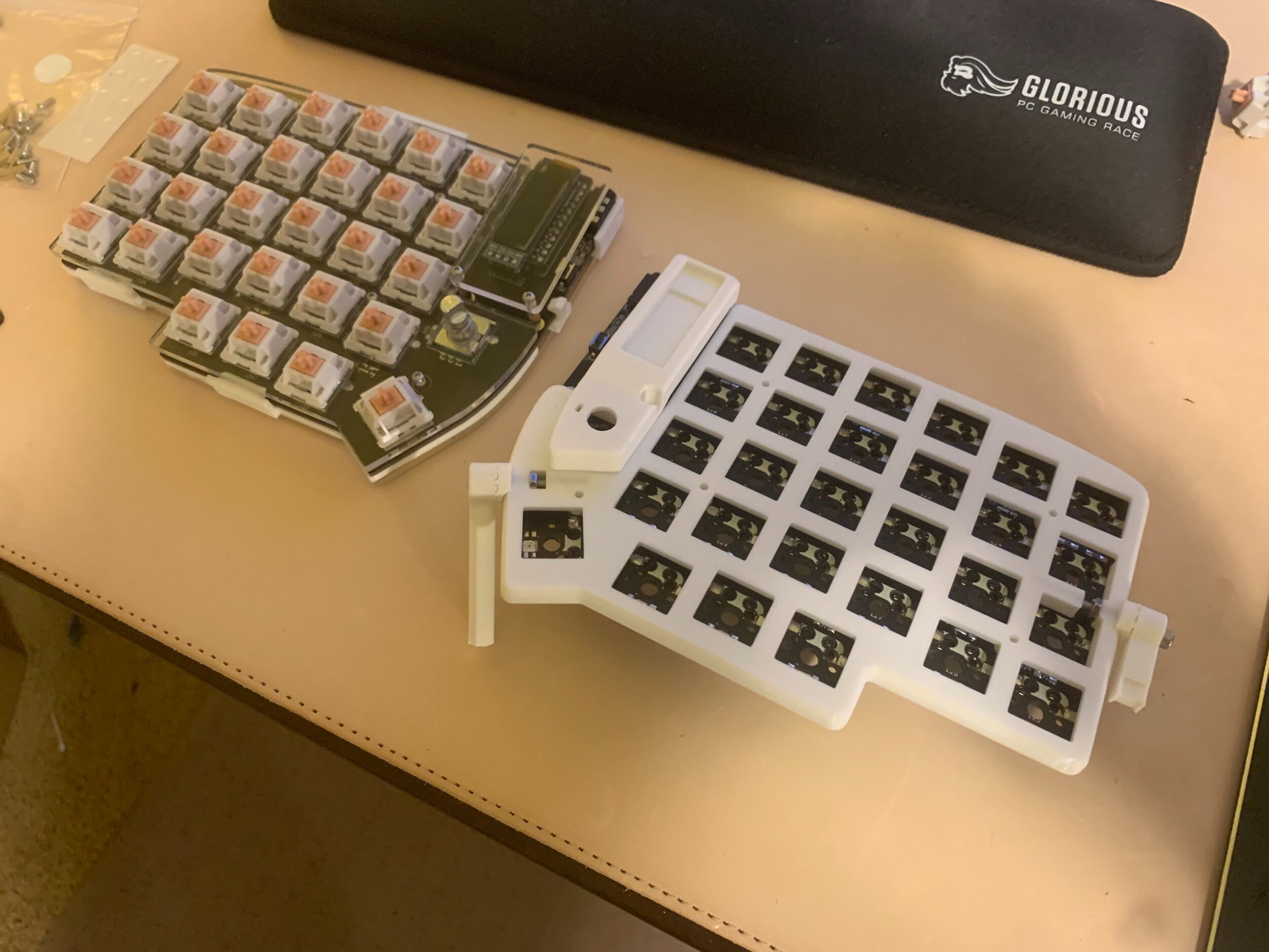
TRRS, Reset Switch, MCUs, and OLEDs
After the components on the back of the board are all soldered, the board will need to be flipped in order to solder the front components. The TRRS needs to be soldered, and the reset button does as well. All that is left now is the MCU and OLED, and to me, it’s a no brainer to have socketed MCUs. Your Pro Micro may die someday, there might be a new revision, or even a completely new processor. The ability to easily swap it out and not have to desolder all 24 pins is a life saver and an extra step that I would say is worth the hassle. If you were wondering what the diode legs were for, this is it. I also did the same thing for my OLED screens, so if one were to burn out for whatever reason I could just easily replace it. Something to note is, if you want to use OLEDs, you will need to bridge the solder points right above the 4 pin OLED holes or it won’t work.
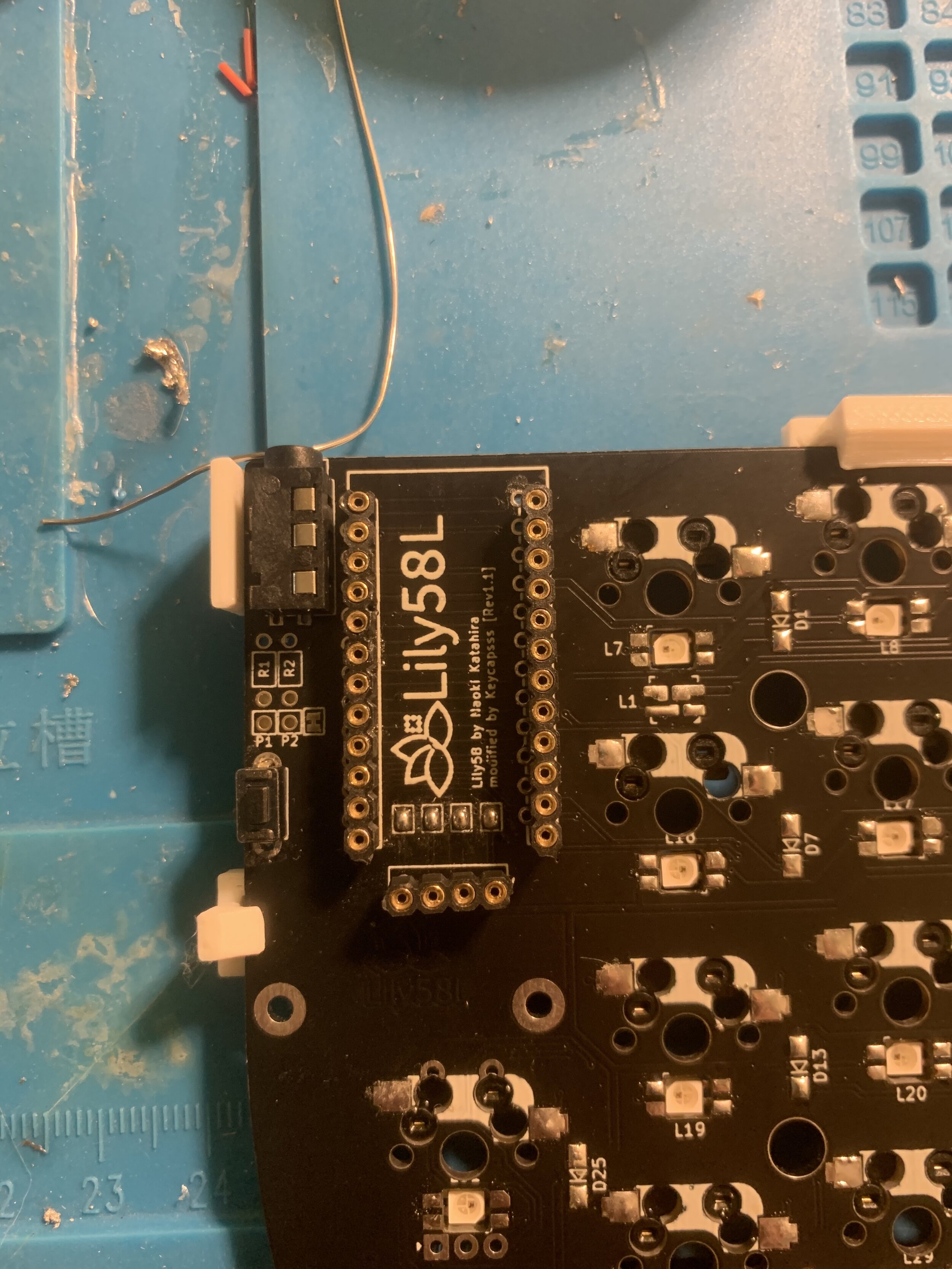
Soldering the sockets can be a bit tricky. You want the socket to be flat against the PCB as possible, I’ve found that using masking tape or blue tape makes this process easier. Just fit the two sockets into the correct holes, tape it down with some blue tape and you should be able to solder them easily. I always start with solder each end of the sockets first, applying some pressure to make sure things are flush. While soldering, you want to be careful not to connect any solder joints as this can cause issues with the keys not working properly. Less is more in this case when soldering. You want just enough that the pins on the socket make contact with the PCB.
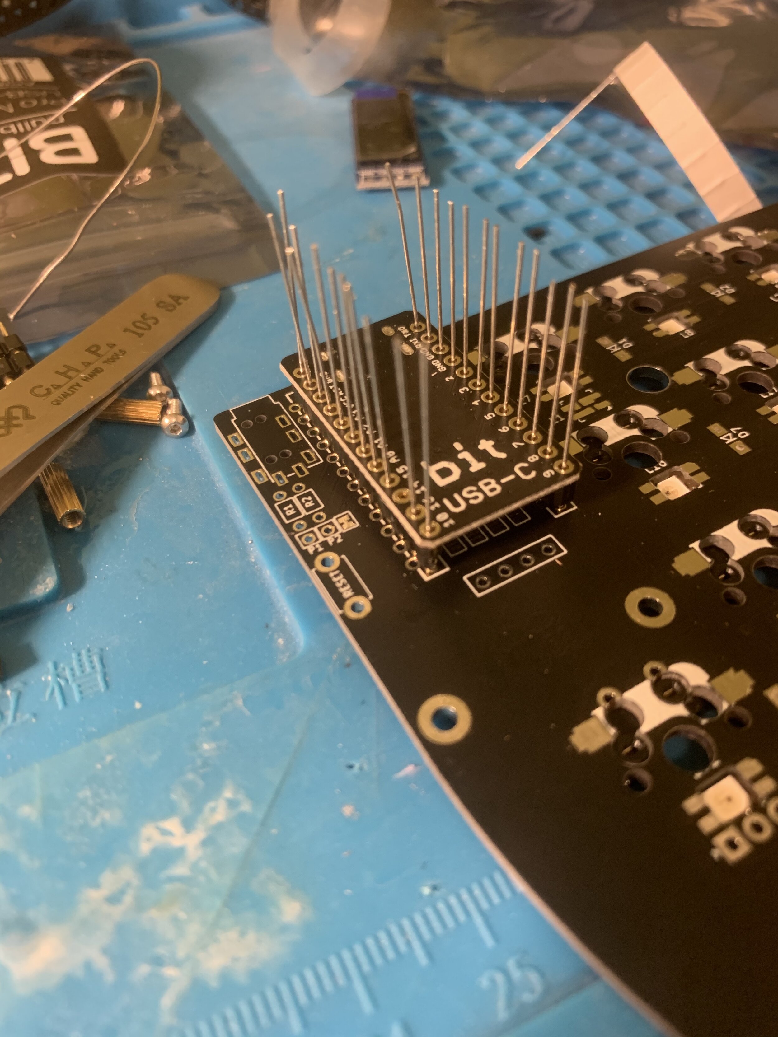
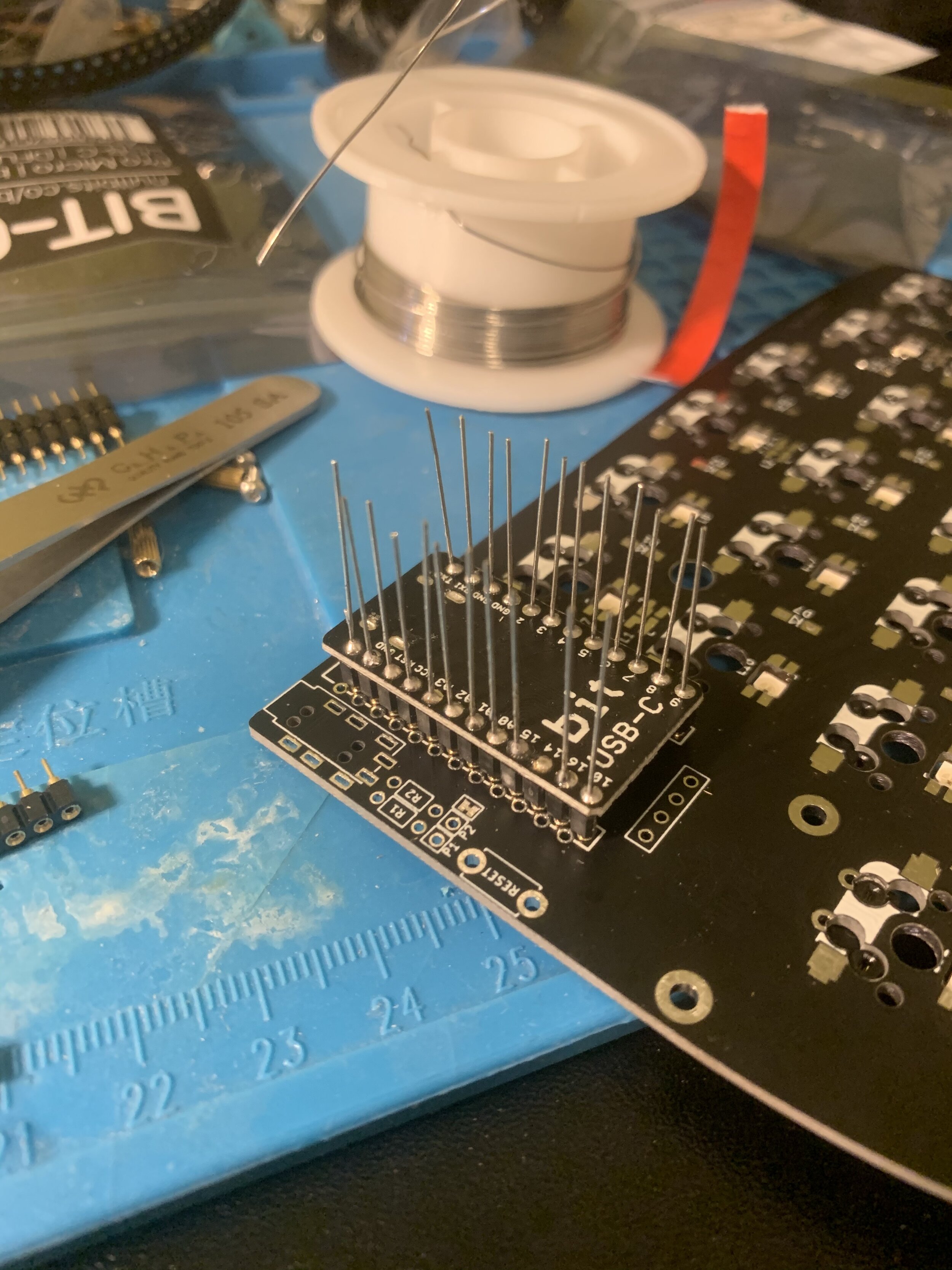
The second part of this is soldering the diode legs and the MCU. First, you’ll need to use some flush cutters to cut the diode legs, you can either just cut 12 legs and cut those 12 legs in half or cut 24 legs. Once those are cut, set them aside. My recommendation is that you place the MCU on top of the sockets and then stick a diode leg through the MCU hole and make sure it lines up with the socket holes. Again, I like to stick legs at in the first and last hole. Doing this provides stability and helps you line up the rest of the holes, after you’re done make sure the legs are in as deep as they can be. Be careful as to not puncture your finger during this process as the legs can be sharp. When soldering the diode legs to the MCU, you want to use as little solder as possible again. If you use too much solder you risk the solder connecting the diode leg to the socket, less is more. Once all the legs have been soldered, use a pair of flush cutters and cut the legs as close to the solder points as possible, this will leave your MCU looking nice and clean.
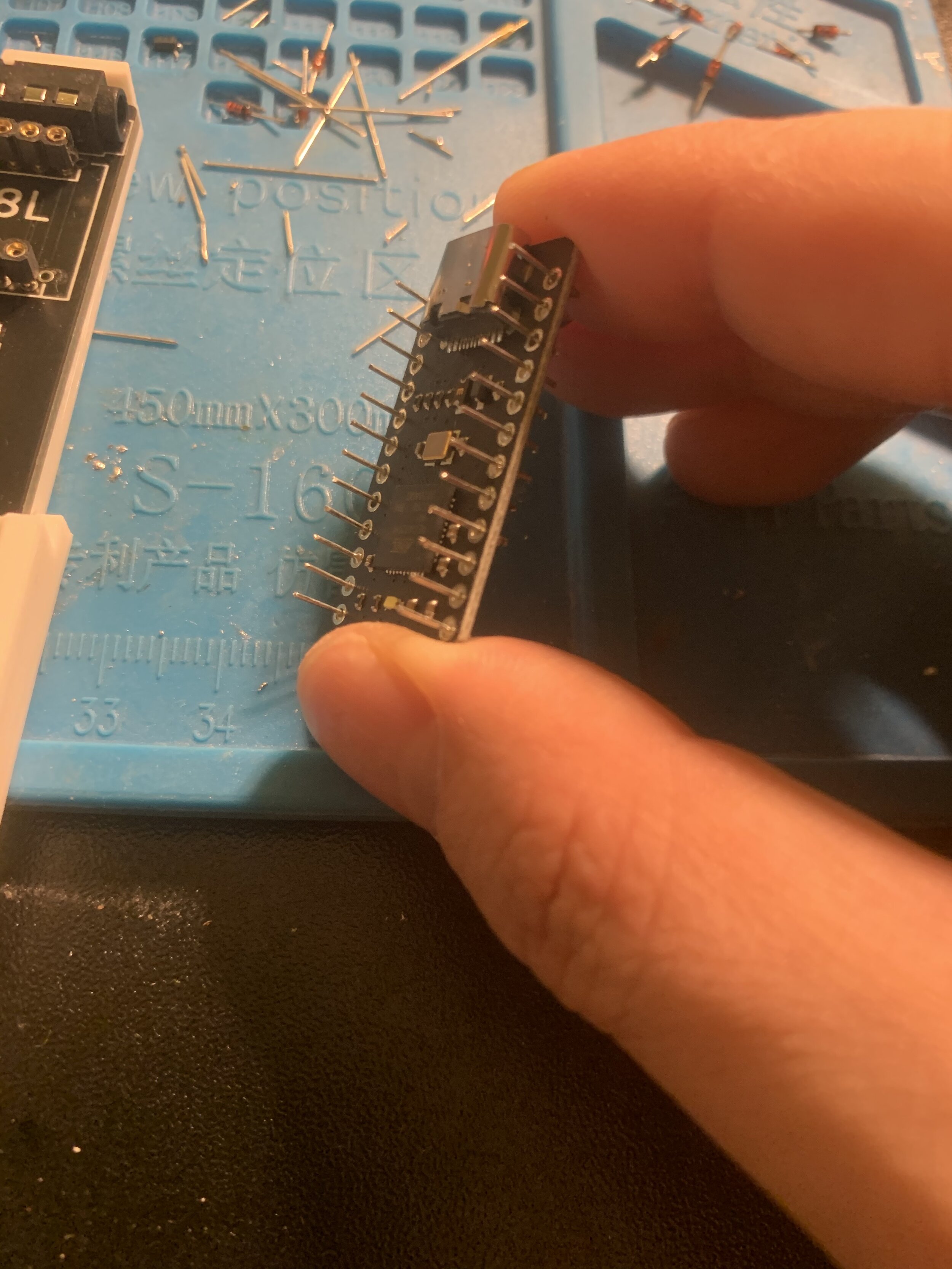
You can at this point move on to soldering the OLED sockets and the OLED module itself, just like you did the MCU. Something you can also try is making sure the MCU can actually be removed, please note that you risk bending your pins if you don’t remove it correctly. You need to put equal pressure on both sides as you try to wiggle the MCU from the sockets. Once you have the OLED module also soldered, you’re ready to test everything.
Plugging in the Lily58
Depending on the MCU you use, it may have came preloaded with a firmware, I used the Nullbits Bit-C which comes with nothing on it. You want to grab the appropriate firmware for your board. Depending on the vendor, they may have prebuilt firmwares already that you can grab from their perspective Githubs. I’m not going to get into building firmwares or customizing them in this guide. Remember that both sides need to be flashed with the same firmware.
Once you have your Lily58 plugged into your computer, you’ll need to flash your MCU. I use QMK toolbox, open the firmware you downloaded and want to use, press the reset button the board and it should go into DFU mode, press the flash button. The board may take a few seconds to flash and you’ll see the status on the QMK Toolbox window. If you have OLEDs and the firmware you’re using is setup to use them, you' should see things like the name of the reversion, what layer you’re in, etc. Once it has been flashed you can try testing the board to see if all the keys work. I usually do this process with each side of the board. I go on Keyboard tester and I use a pair of tweezers to touch solder points on each Kailh hot swap socket to see if it registers a key. If all the hot swap sockets register a key, I flash the other side of the board with the same firmware and repeat the test. If all the keys register on both sides, you’re ready to add the case, switches, and the TRRS cable to connect both.

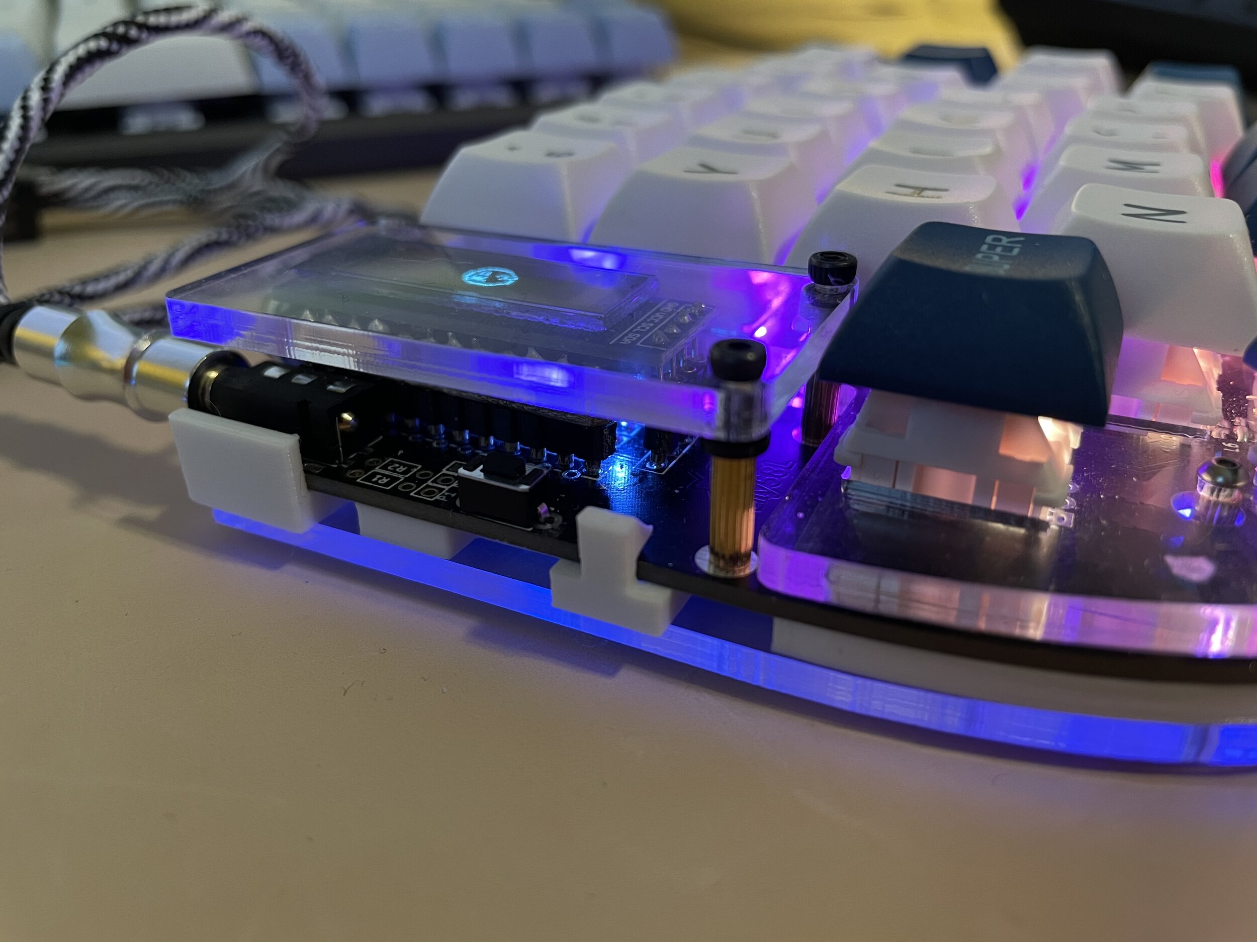
Lily58 Cases
There are a lot of different cases out there, some vendors will sell their Lily58 PCBs in a kit that includes a case, others do not. In my case, my PCB did not come with a case so I had to buy one. I decided to go with an all clear acrylic sandwich case which consists of the top plate and bottom plate. I also played around with the idea of 3D printing a case but decided to use the acrylic case instead. One thing to note is that since we are using sockets for the OLEDs, the stand offs that came with the board may not be tall enough to have proper clearance for the OLED modules. This was the case for my boards, so what I ended up doing is using 2x M2x8mm bolts and 2x M2 washers to give just enough clearance, this was an easy solution because I already had these on hand and they are easier to find then the actual standoffs from my searching. The OLED covers aren’t necessary but they add a nice touch. The case is necessary to provide some stability and also helps so the switches aren’t just sitting on the PCB and can easily fall out. Once the switches have been placed, go ahead and use the keyboard test website again to test each key to make sure they work. In my experience, sometimes you get a bent pin and a key won’t register or you just have a bad switch. Try all the keys and verify they work on both sides of the board. If everything works as it should, time for some keycaps.
Lily58 assembled
If you noticed on my keyboard I’m using what would be considered “Immoral Panda” switches, they feel pretty close to real Holy Panda switches, but are way cheaper. They can be found on AliExpress for around $35. They’re nice and tactile, the spring feels great and they’re not as noisy as my usual Kailh Box Whites that I use on my Preonic.
Assembling the Lily58 is fairly easy. I always put switches at each corner of the top plate and then press the plate into the PCB making sure the pins all align. After doing that I inset the stand offs and screw on the bottom plate. Once both plates are attached to the PCB, you can start plugging in all the switches. I always do one last keyboard test after the switches are plugged in to make sure that the switch pins are inserted properly and are not bent. As soon as I can confirm that everything is working, I start putting keycaps on. For this build I am using some cheap DSA keycaps from AliExpress that cost me around $34, they work find and I like that they are all the same height.

DSA Keycaps
Conclusion
With the keyboard all assembled and working I had to start learning how to type on my new split keyboard. It took some time to get my speed back but honestly I love the ability to move the different sides around so I can be more comfortable. After typing on my Lily58 for over a month, I now feel like my Preonic is too cramp. There’s a part of me that wishes I would’ve jumped start to a Lily58 when I was exploring the idea of an ortho keyboard. Although my setup isn’t perfect, It works for me and at the end of the day, that should be what matters the most, if a setup works well for you. You don’t need to spend $500+ on a mech keyboard. I hope this guide helps anyone who comes across it. I know there are Github guides out there but I just didn’t feel like they were detailed enough and being a visual person, it really helps to have more pictures. If you found that this guide helped you out, consider donating with the link at the bottom of the page. It helps me to keep the site up and continue to bring more content.

My Lily58L and Preonic Keyboard